TRON 2 · DOCUMENTATION
Components & ports
Excerpted from the supplied English User Manual v1.4. Chinese editorial corrections and later confirmations may not be synchronized. Check the Chinese reference where the two differ.
Configuration: dual-arm details apply only to dual-arm/mobile dual-arm robots. Older instructions differ in power timing, light names and homing motion; check the operational guidance and version notes on this page.
1.4 Body Components and Ports
Body Components
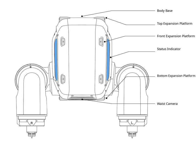
| Component/Ports | Function Description | Component/Ports | Function Description |
|---|---|---|---|
| Status Indicator | Displays overall robot status, including mode status, fault status, low-battery reminders, etc. | Peripheral Expansion Platform | Includes peripheral expansion platforms at the top, front, and bottom. All threaded holes are M4 and are used to mount external expansion devices. |
Robot Body Receptacle Interfaces
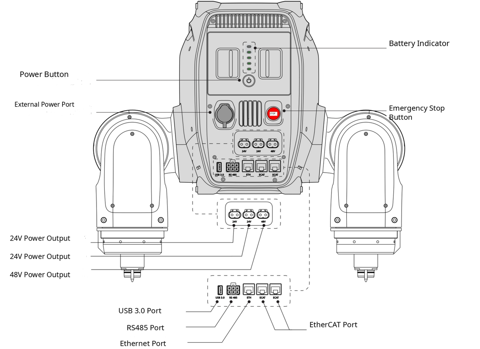
| Component/Ports | Function Description | Component/Ports | Function Description |
|---|---|---|---|
| Power Button | Used to power the robot on/off | Battery Level Indicator | Displays the current robot battery level |
| External Power Ports | Used to connect an external power adapter | Emergency Stop Button | In an emergency, press this button to enter torque-off mode, cutting motor power |
| 24 V Power Output Ports | LCB female connector, stable 24 V DC output, rated output 5 A, maximum output 20 A | 48 V Power Output Port | LCB female connector, stable 48 V DC output, rated output 10 A, maximum output 20 A |
| USB 3.0 Ports | USB-A 3.0, available for external device expansion | Ethernet Ports | Gigabit Ethernet port for connecting a computer, router, or other communication module |
| RS485 Ports | Used to expand external devices | EtherCAT Ports | Used to expand external devices |
Developer Expansion Module Ports
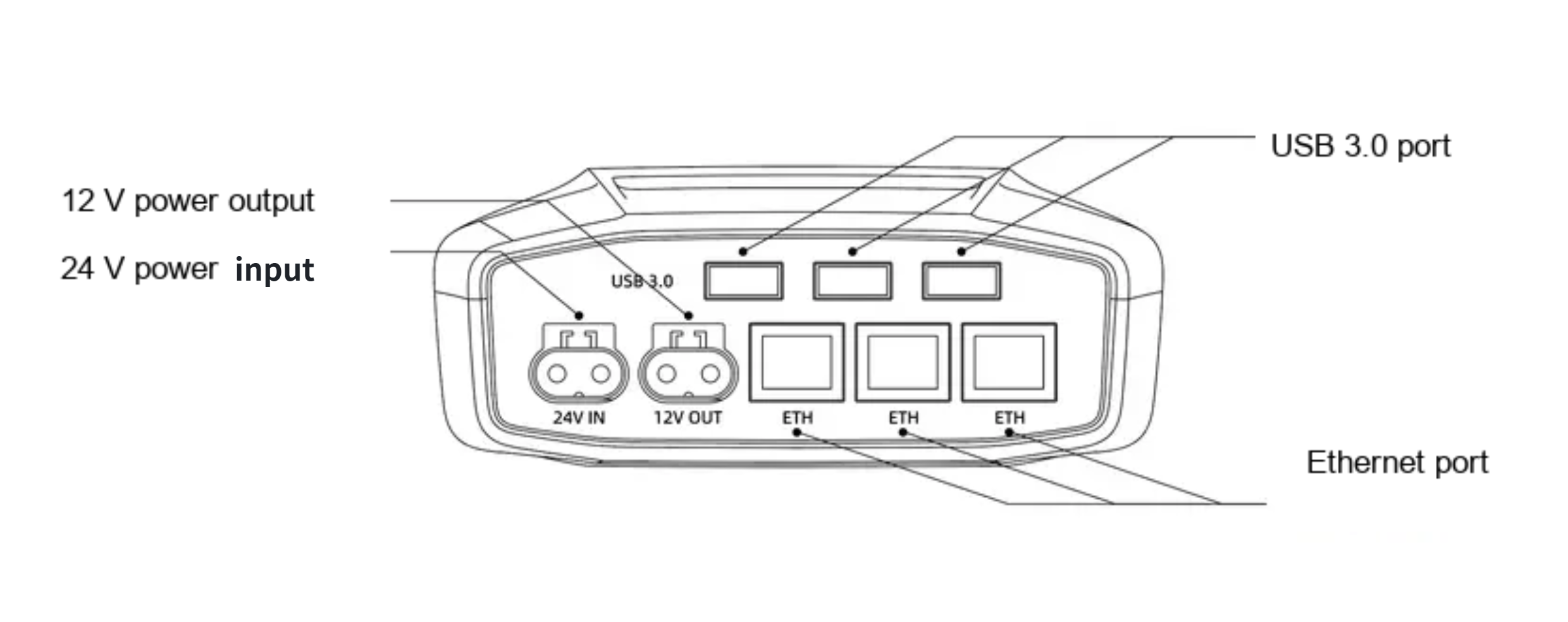
| Component/Interface | Function Description | Component/Ports | Function Description |
|---|---|---|---|
| 12 V Power Output Port | LCB female connector, stable 12 V DC output, maximum output current 5 A | Ethernet Interface | Gigabit Ethernet port |
Dual-arm configuration details · 1.4.1 Body Components
| Component/Port | Function | Component/Port | Function |
|---|---|---|---|
| Status Indicator | Displays robot status, including operating mode, faults, and Low Battery Warnings | Peripheral Expansion Platform | Provides top, front, and bottom mounting areas. All threaded holes are M4 and are used to secure external devices. |
Dual-arm configuration details · 1.4.2 Robot Body Receptacle Ports
| Component/Port | Function | Component/Port | Function |
|---|---|---|---|
| Power Button | Powers the robot on or off | Battery Level Indicator | Displays the current robot Battery Level |
| External Power Supply Port | Connects the external Power Adapter | Emergency Stop Button | Cuts power to the motors and places the robot in Torque-Off Mode |
| 24 V Power Output Port | LCB female connector; regulated 24 V DC output; rated current 5 A; maximum current 20 A | 48 V Power Output Port | LCB female connector; regulated 48 V DC output; rated current 10 A; maximum current 20 A |
| USB 3.0 Port | USB-A 3.0 port for external devices | Ethernet Port | Gigabit Ethernet port for a computer, router, or other communication module |
| RS485 Port | Connects external devices | EtherCAT Port | Connects external devices |
Dual-arm configuration details · 1.4.3 Developer Expansion Module Ports
| Component/Port | Function | Component/Port | Function |
|---|---|---|---|
| 12 V Power Output Port | LCB female connector; regulated 12 V DC output; maximum output current 5 A | Ethernet Port | Gigabit Ethernet port |
NEXTFrames & joint limits