TRON 2 DOCS
Products/TRON 2/Hardware reference
TRON 2 · DOCUMENTATION

Frames & joint limits

Check scope below

Excerpted from the supplied English User Manual v1.4. Chinese editorial corrections and later confirmations may not be synchronized. Check the Chinese reference where the two differ.

Configuration: dual-arm details apply only to dual-arm/mobile dual-arm robots. Older instructions differ in power timing, light names and homing motion; check the operational guidance and version notes on this page.

1.5 Coordinate Frames and Joint Limits

Dual-Arms Configuration

When all joints are at zero degrees, their joint coordinate frames are shown below. Red indicates the x-axis, green indicates the y-axis, and blue indicates the z-axis.
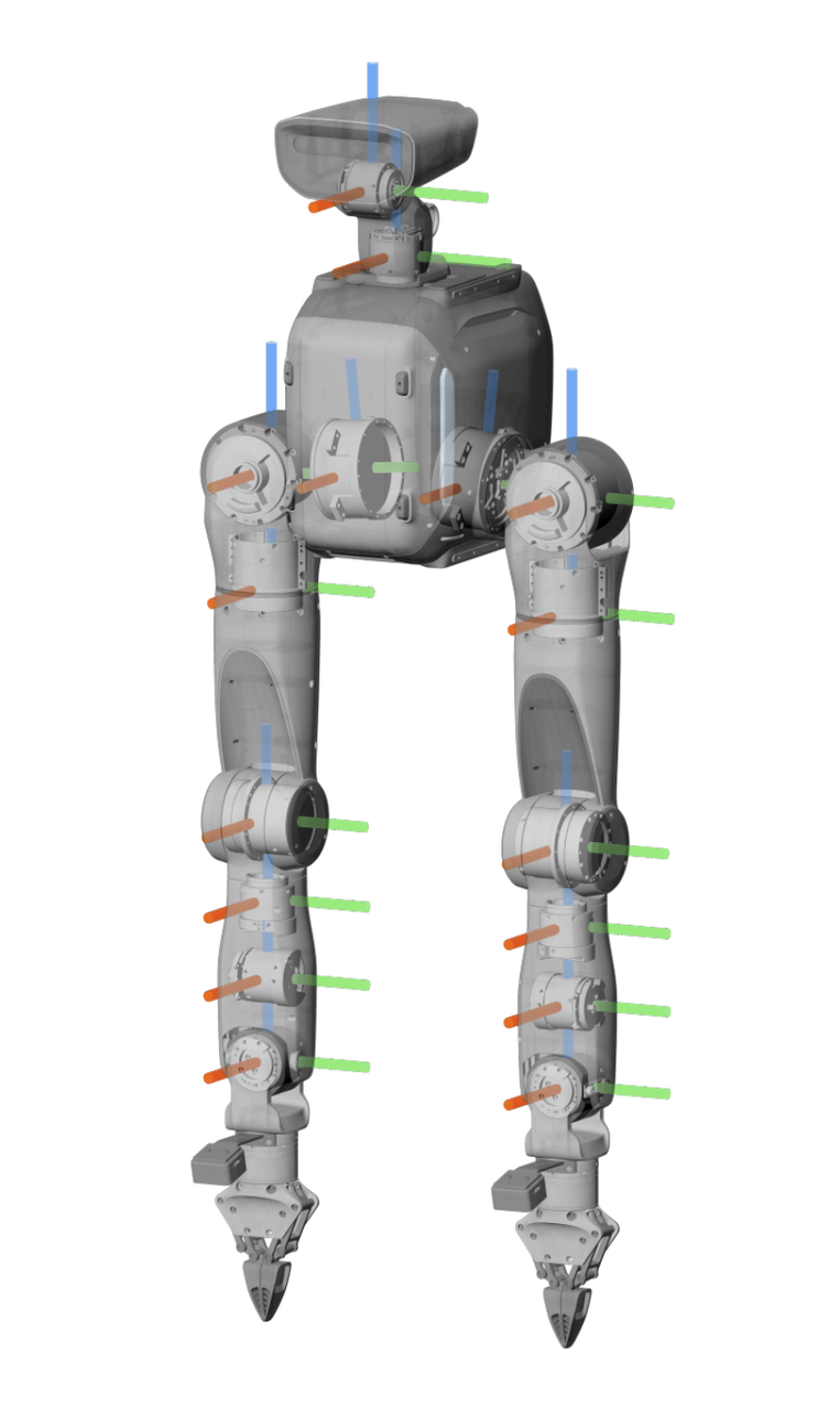
Product manual illustration

Joint numbers and limits are shown below.
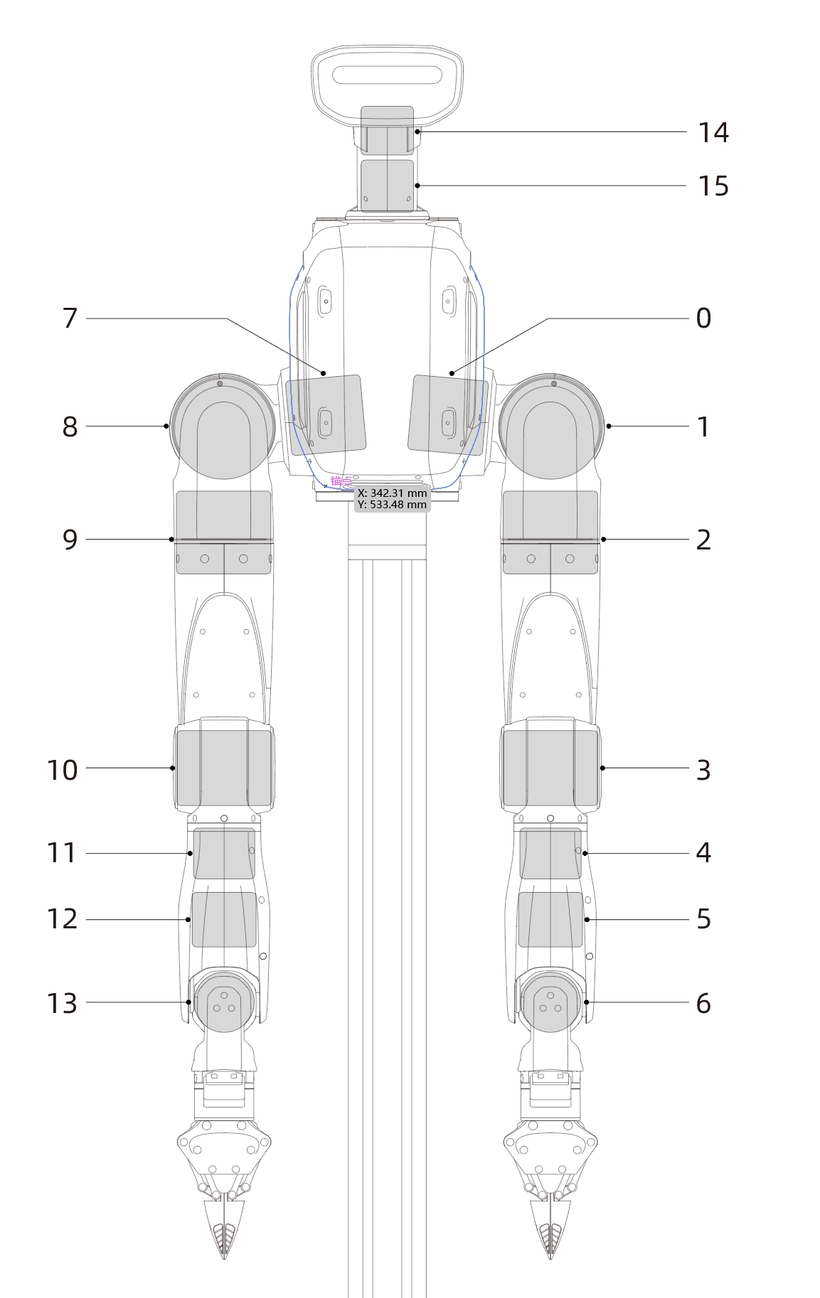
joint_limit.png
Joint
No.
English Joint NameLimits (deg)Limits (rad)
Lower LimitUpper LimitLower LimitUpper Limit
0proximal_pitch_L_Joint-180149-3.142.60
1proximal_roll_L_Joint-15183-0.263.22
2proximal_yaw_L_Joint-21085-3.661.48
3elbow_L_Joint-15015-2.610.26
4wrist_yaw_L_Joint-10080-1.741.39
5wrist_pitch_L_Joint-4545-0.780.78
6wrist_roll_L_Joint-9090-1.571.57
7proximal_pitch_R_Joint-180149-3.142.60
8proximal_roll_R_Joint-18315-3.220.26
9proximal_yaw_R_Joint-85210-1.483.66
10elbow_R_Joint-15015-2.610.26
11wrist_yaw_R_Joint-80100-1.391.74
12wrist_pitch_R_Joint-4545-0.780.78
13wrist_roll_R_Joint-9090-1.571.57
14head_pitch_Joint-4560-0.781.04
15head_yaw_Joint-9090-1.571.57

Sole/Wheeled Configuration

When all joints are at zero degrees, their joint coordinate frames are shown below. Red indicates the x-axis, green indicates the y-axis, and blue indicates the z-axis.
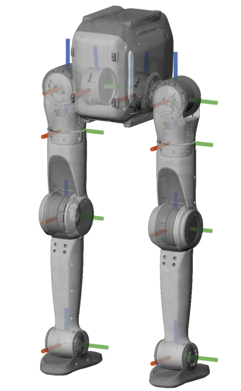
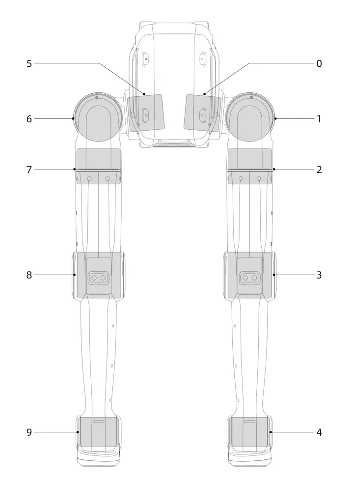
img_v3_0211n_7d399328-d76b-443a-bc6a-639081a8702g.jpg
joint_limit.png
Joint
No.
English Joint NameLimits (deg)Limits (rad)
Lower LimitUpper LimitLower LimitUpper Limit
0proximal_pitch_L_Joint-180149-3.142.60
1proximal_roll_L_Joint-15183-0.263.19
2proximal_yaw_L_Joint-21085-3.661.48
3knee_L_Joint-15015-2.610.26
4ankle_pitch_L_Joint-9797-1.691.69
wheel_L_Joint∞∞∞∞
5proximal_pitch_R_Joint-180149-3.142.60
6proximal_roll_R_Joint-18315-3.190.26
7proximal_yaw_R_Joint-85210-1.483.66
8knee_R_Joint-15015-2.610.26
9ankle_pitch_R_Joint-9797-1.691.69
wheel_R_Joint∞∞∞∞

Dual-arm configuration details · 1.5 Coordinate Frames and Joint Limits

  • When all joints of the Dual-Arm Robot are at zero degrees, their coordinate frames are as shown below. Red indicates the x-axis, green indicates the y-axis, and blue indicates the z-axis.

  • The joint numbers and limits are shown below:

joint_limit.png
Joint
No.
English Joint NameLimits (deg)Limits (rad)
Lower LimitUpper LimitLower LimitUpper Limit
0proximal_pitch_L_Joint-180149-3.142.60
1proximal_roll_L_Joint-15183-0.263.19
2proximal_yaw_L_Joint-21085-3.661.48
3elbow_L_Joint-15015-2.610.26
4wrist_yaw_L_Joint-10080-1.741.39
5wrist_pitch_L_Joint-4545-0.780.78
6wrist_roll_L_Joint-9090-1.571.57
7proximal_pitch_R_Joint-180149-3.142.60
8proximal_roll_R_Joint-18315-3.190.26
9proximal_yaw_R_Joint-85210-1.483.66
10elbow_R_Joint-15015-2.610.26
11wrist_yaw_R_Joint-80100-1.391.74
12wrist_pitch_R_Joint-4545-0.780.78
13wrist_roll_R_Joint-9090-1.571.57
14head_pitch_Joint-4560-0.781.04
15head_yaw_Joint-9090-1.571.57
NEXTBattery & charging